Platform Integration Aspects: Custom Hardware Integration
Integrating an Embedded Wizard GUI application on custom hardware requires careful planning and systematic implementation. This article provides a comprehensive guide through the essential steps, from initial hardware assessment to final application deployment.
TIP
This article focuses primarily on microcontroller (MCU) based systems. For microprocessor (MPU) based systems running Linux, many integration steps are significantly simplified as the operating system handles low-level hardware initialization, memory management, and device drivers.
Select Appropriate Build Environment
The first and most critical step is selecting the right Build Environment that matches your custom hardware as closely as possible.
IMPORTANT
Before proceeding with custom hardware integration, ensure you have an official reference board (evaluation board) and have successfully completed the corresponding Getting Started guide. This working reference system serves as your baseline for comparison and troubleshooting during custom hardware integration. All Embedded Wizard Build Environments serve as reference implementations and should be used as starting points for custom hardware integration.
Consider the following criteria when selecting your Build Environment:
•CPU Architecture - Cortex-M families (e.g. M4, M7, M33, M55, M85), Cortex-A families, or other supported architectures
•Operating System - Bare metal, FreeRTOS, Linux, or other supported systems
•Display Interface - RGB parallel, MIPI DSI, SPI, or other display connections
•Graphics Acceleration - Hardware graphics acceleration capabilities
•Memory Configuration - Available RAM and Flash memory sizes
Each Build Environment contains reference implementations for display drivers, touch drivers, and system integration code. These serve as templates that can be adapted to your specific hardware requirements.
Configure System Parameters
Configure the system parameters in the ewconfig.h file according to your hardware specifications. This configuration file contains critical settings that must match your hardware capabilities before any integration work can begin.
The most important configuration areas are Memory Configuration and Display Configuration. Proper configuration of these parameters is essential for stable operation of your GUI application.
For detailed information about all available configuration options and their effects on your specific hardware, refer to Target Configuration.
IMPORTANT
Correct system configuration is the foundation of successful hardware integration. Misconfigured parameters will cause crashes, poor performance, or display artifacts.
Establish Debug Console Connection
Adapt the /TargetSpecific/ew_bsp_console.c file to establish a reliable debug console connection:
★Configure the serial interface (UART) parameters for your hardware.
★Implement or adapt the console initialization and output functions.
★Test the console connection with simple debug messages before proceeding.
For MCU-based systems, this typically involves configuring a UART interface. For MPU-based systems running Linux, SSH connections are commonly used for remote debugging and console access.
IMPORTANT
A working debug console is essential for monitoring the integration process and diagnosing issues. Every Build Environment contains detailed instructions for console setup.
System Initialization (MCU targets only)
For microcontroller-based systems, adapt the /TargetSpecific/ew_bsp_system.c file:
★Configure system clocks, PLL settings, and peripheral clocks.
★Initialize memory controllers (SDRAM, Flash) with proper timing parameters according to your memory specifications.
★Configure Memory Protection Unit (MPU) settings for systems with MPU support (e.g. Cortex-M7) - ensure MPU regions match your custom hardware's memory layout.
★Configure power management and low-power modes if required.
For additional information about system integration, refer to Main Loop concepts.
Verify Memory Subsystem
After system initialization is complete and SDRAM timing parameters are properly configured, verify that your memory subsystem is working correctly. Memory issues are among the most common causes of integration problems.
Use a comprehensive SDRAM test that writes incrementing data patterns to consecutive memory addresses and reads them back after exponentially increasing delay times to verify refresh functionality. Put the following code snippet into your ewmain.c file and call the test function just before the initialization of the memory manager:
void TestSDRAM( void ) { unsigned char* ptr; unsigned char data; unsigned int count; unsigned int delay = 1; EwPrint( "Check memory at address 0x%08X with size 0x%08X\r\n", EW_MEMORY_POOL_ADDR, EW_MEMORY_POOL_SIZE ); EwPrint( "Write test pattern to SDRAM... " ); ptr = (unsigned char*)( EW_MEMORY_POOL_ADDR ); data = 0x00; count = EW_MEMORY_POOL_SIZE; while ( count-- ) { *ptr++ = data++; if ( data >= 253 ) data = 0; } EwPrint( "[OK]\r\n" ); while ( delay < 256 ) { EwPrint( "Read test pattern from SDRAM... " ); ptr = (unsigned char*)( EW_MEMORY_POOL_ADDR ); data = 0x00; count = EW_MEMORY_POOL_SIZE; while ( count-- ) { if ( *ptr++ != data++ ) EwPrint( "Error at address 0x%08X\r\n", ptr-1 ); if ( data >= 253 ) data = 0; } EwPrint( "[OK]\r\n" ); EwPrint( "Waiting for %d seconds...", delay ); EwBspOsDelay( delay * 1000 ); EwPrint( "\r\n" ); delay *= 2; } }
The incrementing data pattern and exponentially increasing delay times are essential for detecting address line problems and verifying that SDRAM refresh is working correctly.
IMPORTANT
A faulty or incorrectly configured memory subsystem will cause unpredictable behavior, crashes, and graphical artifacts. Always ensure memory stability before proceeding with GUI integration.
Display Driver Integration
Adapt the /TargetSpecific/ew_bsp_display.c file for your specific display hardware:
★Configure display parameters (resolution, color format, timing) according to your display datasheet and display controller specifications. Ensure that the display interface type (parallel RGB, MIPI DSI, SPI, etc.) matches your reference platform, or adapt the driver accordingly.
★Implement or adapt the display controller initialization sequence. Verify that all display control lines (RESET, backlight, chip select, data/command) are initialized correctly to ensure the display is ready to use.
★Verify frame buffer memory allocation and addressing.
★Test basic display functionality by filling the framebuffer with memset() using different color values.
★Use the /Examples/ScreenOrientation and /Examples/ColorFormats examples to verify proper display integration and calibrate display parameters. If colors appear incorrect, check the color channel assignment in ewextgfx.h. Review display configuration settings in ewconfig.h.
For background information about display integration concepts, see Framebuffer Concepts.
Touch Driver Integration
Adapt the /TargetSpecific/ew_bsp_touch.c file for your touch controller:
★Implement touch controller initialization and communication protocol (I2C, SPI, etc.) according to your touch controller datasheet and driver specifications.
★Use the debugging macro EW_PRINT_TOUCH_DATA (configured in ewconfig.h) to verify that raw touch data from the driver is correct and complete.
★Use the debugging macro EW_PRINT_TOUCH_EVENTS (configured in ewconfig.h) to verify that processed touch events are properly mapped and sent to the GUI application.
★Use the /Examples/ScreenOrientation example to test and calibrate touch functionality - it provides immediate visual feedback for touch coordinate verification. Review touchscreen configuration settings in ewconfig.h for coordinate mapping and orientation.
IMPORTANT
For proper functioning of all touch controls, every touch cycle for each finger must be complete: starting with one DOWN event, followed by 0...n MOVE events, and finalized with one UP event. This sequence is essential and mandatory for providing touch events to the GUI application.
Reading the raw touch data from the hardware can be implemented either polling-based (checking controller registers) or interrupt-based (using hardware interrupts), depending on your hardware design and performance requirements.
The remaining touch functionality (coordinate mapping, event handling, coordinate transformation) is typically already implemented in the function EwBspTouchGetEvents() in the module ew_bsp_touch.c and may only require minor parameter adjustments. For more details about touch debugging macros, see Target Configuration.
Operating System Integration (MCU targets only)
If you want to change from the default operating system (usually FreeRTOS) to a different OS, adapt all functions within the file /TargetSpecific/ew_bsp_os.c to your particular operating system:
★Implement OS-specific task/thread creation and management functions.
★Adapt timing functions and system tick implementation for your OS.
★Modify inter-task communication mechanisms (semaphores, mutexes).
★Update the makefile/project file to link with your OS libraries and include paths.
IMPORTANT
Ensure that the main GUI application runs in a single thread context, as Embedded Wizard is not thread-safe. Use appropriate synchronization mechanisms when communicating between threads. For safe communication from worker threads to the GUI thread, use the provided functions EwInvoke() and EwInvokeCopy().
Initial Testing with Simple Examples
Start the integration process with simple test applications rather than complex GUI projects:
ScreenOrientation Example
Use the /Examples/ScreenOrientation example as your first test:
★Contains simple animations to verify system tick functionality
★Tests basic display update mechanisms
★Can be used for touch calibration and coordinate verification
★Provides immediate visual feedback about system integration status
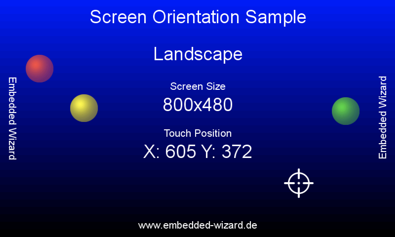
The ScreenOrientation example demonstrates simple animations and touch response, making it ideal for verifying system tick functionality and touch calibration during hardware integration.
ColorFormats Example
Use the /Examples/ColorFormats example to verify display quality:
★Displays color gradients to test all display bits
★Helps identify color format and bit ordering issues
★Reveals display timing and signal integrity problems
★Validates frame buffer addressing and memory access

The ColorFormats example displays various color gradients and patterns, making it perfect for testing display bit integrity and color format configuration during hardware integration.
Follow these steps with increasing compexity:
★Start with the ScreenOrientation example to verify basic functionality.
★Proceed to ColorFormats example to test display quality.
★Only after successful testing of simple examples, move to more complex GUI applications.
Memory Layout Planning
Plan your memory layout carefully to ensure optimal performance:
•Frame Buffer Placement - Follow semiconductor manufacturer recommendations for optimal framebuffer memory placement (e.g. ST's AN4861 or similar application notes from your chip vendor)
•Heap Configuration - Reserve sufficient memory for dynamic allocations. Monitor actual heap usage during development and add safety margin to prevent fragmentation and out-of-memory conditions
•Stack Size - Ensure adequate stack space for GUI operations. For typical GUI applications, reserve at least 4-8 KB stack per task/thread
•Cache Considerations - Configure memory regions for optimal cache performance. Framebuffers can be placed in cacheable memory regions, which provides significant performance benefits for CPU-based drawing operations. The Graphics Engine includes the necessary cache management mechanisms (clean/invalidate). Consult your MCU manufacturer's documentation for recommended cache configuration and memory region setup
TIP
For detailed memory usage information and optimization strategies, see Memory Footprint.
Performance Monitoring and Optimization
Monitor system performance during integration to ensure optimal operation:
•CPU Load Monitoring - Use the /Examples/GraphicsAccelerator example to measure rendering performance
•Memory Usage - Monitor heap utilization and detect memory leaks - see Monitoring the memory usage
•Frame Rate Analysis - Verify that achieved frame rates meet expectations and that graphics are displayed without flickering. Adjust the target frame rate to a realistic value - an unnecessarily high target frame rate consumes excessive memory bandwidth without benefit
•Power Consumption - Verify power management implementation
For detailed performance optimization strategies covering hardware architecture, software configuration, and GUI design, see Performance Optimization Guide.
Debug Setup Enhancement
Beyond basic console output, consider additional debugging capabilities:
•JTAG/SWD Connection - For low-level debugging and memory inspection
•Logic Analyzer - For analyzing display and touch interface signals
•Oscilloscope - For verifying timing parameters and signal quality
•Performance Counters - For detailed CPU and memory performance analysis
Power Management Considerations
Implement appropriate power management for your application:
★Configure CPU clock speeds for optimal performance vs. power consumption.
★Implement display backlight control and automatic dimming.
★Consider touch controller power modes and wake-up functionality.
★Test GUI behavior during power transitions and voltage variations.
IMPORTANT
Unstable power supply is a common cause of integration problems. Ensure adequate power supply design and proper decoupling capacitors.
Troubleshooting Common Issues
If you encounter problems during integration, check the Error and Warning Codes documentation for detailed error descriptions and solutions. Common integration issues include:
•Memory corruption - Usually caused by incorrect SDRAM configuration
•Display artifacts - Often related to timing parameters, signal integrity, or insufficient memory bandwidth causing buffer underruns that result in flickering content for individual frames. Reducing the pixel clock frequency (down to the lower limit according to display specifications) can help alleviate or eliminate memory bandwidth issues
•Touch coordinate problems - Typically caused by incorrect coordinate mapping between raw touch driver data and GUI application touch events, or incomplete touch event sequences (missing DOWN/UP events)
•Performance issues - May indicate insufficient CPU speed or memory bandwidth
•System crashes - Often related to stack overflow, out-of-memory conditions, or interrupt configuration. Use debugger stack traces and memory monitoring to identify root causes
TIP
Always verify each integration step thoroughly before proceeding to the next. This systematic approach helps isolate problems and reduces debugging time.
Integration Testing Strategy
Follow a systematic approach for testing your integration:
★Hardware Verification - Test memory, display, and touch hardware independently
★Basic System Test - Verify system tick, console output, and basic functionality
★Simple GUI Test - Run ScreenOrientation and ColorFormats examples
★Touch Integration Test - Verify touch functionality with simple applications
★Performance Test - Run GraphicsAccelerator example to measure performance
★Stress Test - Run complex GUI applications under various conditions. For production systems, perform extended runtime tests (several hours to multiple days) to detect memory leaks, fragmentation, or timing-related issues
★Production Test - Verify functionality under production conditions
By following this systematic approach, you can successfully integrate Embedded Wizard GUI applications on your custom hardware platform while minimizing integration time and avoiding common pitfalls.